The automotive world is rapidly evolving, with technology playing an increasingly crucial role in vehicle design and maintenance. Among the many innovations, Arduino-based diagnostic tools are emerging as powerful allies for both professional mechanics and DIY enthusiasts looking to understand and address vehicle issues. This comprehensive guide delves into the world of Diagnostic Tools For Arduino, providing you with the knowledge and resources to effectively troubleshoot your vehicle.
Why Choose Arduino for Vehicle Diagnostics?
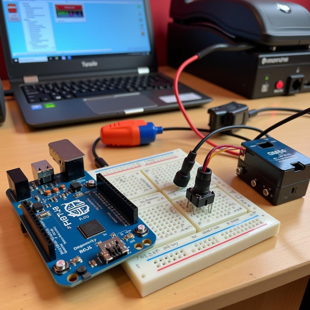
 Arduino Diagnostic Setup
Arduino platforms offer a compelling combination of affordability, flexibility, and a vast online community. These factors make them an ideal choice for building customized diagnostic tools tailored to specific needs. Unlike generic OBD-II scanners, Arduino empowers you to:
- Target Specific Systems: Isolate and monitor specific sensors or systems in your car, focusing your diagnostic efforts.
- Customize Data Display: Develop personalized interfaces to visualize data in a way that makes sense to you.
- Integrate with Other Tools: Combine Arduino with other tools and platforms to create a comprehensive diagnostic ecosystem.
Essential Components for Arduino Vehicle Diagnostics
Before diving into the world of Arduino diagnostics, it’s essential to gather the necessary components:
- Arduino Board: The brain of your diagnostic system. Popular choices include the Arduino Uno and Nano due to their user-friendliness and ample I/O pins.
- Sensors: These are your eyes and ears within the vehicle’s systems. Common sensors include:
- Oxygen Sensor (O2): Monitors the air-fuel mixture for optimal engine performance and emissions.
- Manifold Absolute Pressure (MAP) Sensor: Measures the pressure inside the intake manifold, providing insights into engine load and throttle position.
- Throttle Position Sensor (TPS): Indicates the position of the throttle plate, crucial for fuel injection and ignition timing.
- Coolant Temperature Sensor (CTS): Monitors the engine’s coolant temperature, essential for preventing overheating.
- CAN-BUS Shield: This acts as the bridge between your Arduino and your vehicle’s Controller Area Network (CAN-BUS), allowing you to tap into the wealth of data flowing through it.
- Jumper Wires, Breadboard, Resistors: These are essential for connecting and prototyping your circuits.
- Computer with Arduino IDE: This is where you’ll write, upload, and monitor the code that powers your diagnostic tool.
Getting Started: Reading OBD-II Data with Arduino
The On-Board Diagnostics II (OBD-II) standard provides a standardized way to access vehicle diagnostic information. Here’s a simplified approach to reading OBD-II data using Arduino:
- Connect the CAN-BUS Shield: Attach the shield to your Arduino board, ensuring proper pin alignment.
- Locate the OBD-II Port: Typically located under the dashboard on the driver’s side, the OBD-II port is a 16-pin trapezoidal connector.
- Connect to the OBD-II Port: Use an OBD-II to DB9 cable to connect your CAN-BUS shield to the vehicle’s OBD-II port.
- Upload the Code: Upload a sketch (Arduino code) designed to read OBD-II data. Numerous libraries and code examples are readily available online.
- Monitor the Data: Open the Serial Monitor in the Arduino IDE to view the data streamed from your vehicle’s ECU in real-time.
Advanced Applications: Going Beyond Basic Diagnostics
The true power of Arduino for vehicle diagnostics lies in its ability to go beyond reading standard OBD-II codes. You can:
- Build Custom Dashboards: Create visually appealing and informative dashboards to monitor performance parameters in real-time.
- Log Data for Analysis: Record sensor data over time, enabling you to identify intermittent issues and analyze long-term trends.
- Develop Predictive Maintenance Tools: By analyzing historical data and setting thresholds, you can receive alerts for potential issues before they escalate.
- Experiment with DIY Projects: Explore creative applications such as adding shift lights, performance timers, or even automated features to your vehicle.
Troubleshooting Tips and Considerations
Embarking on DIY vehicle diagnostics can be incredibly rewarding, but it’s important to proceed with caution:
- Start Simple: Begin with basic projects and gradually increase complexity as your skills grow.
- Research Thoroughly: Understand the systems and sensors you’re working with to avoid misinterpreting data or causing damage.
- Double-Check Connections: Ensure all connections are secure and correctly wired to prevent short circuits or inaccurate readings.
- Verify Data Accuracy: Cross-reference data with other diagnostic tools or consult with experienced mechanics to validate your findings.
Conclusion
Arduino-based diagnostic tools offer an accessible and versatile approach to understanding and addressing vehicle issues. By leveraging the power of Arduino, you can delve deeper into your vehicle’s systems, customize your diagnostic approach, and gain invaluable insights into your car’s health. Whether you’re a seasoned mechanic or a car enthusiast, Arduino empowers you to take control of your vehicle’s diagnostics.
Need expert assistance with your automotive diagnostic needs? Contact ScanToolUS at +1 (641) 206-8880 or visit our office at 1615 S Laramie Ave, Cicero, IL 60804, USA. We’re here to help!


